Please call AAAmachine
at 800-996-0070
for any air knocker questions. E-mail
>> No account with us for purchasing? (new customers)
No problem. If you would like to buy Exen Air Knocker products through
internet using your credit card, please visitE-commerce siteas follows.
You can buy Exen Air Knocker through AAA Save Energy/AAAmachine, Inc.Shop On-Line(international Buy-direct E-commerce service powered by BigCommerce) using
your credit card.
*** What is AAA Save Energy / AAAmachine, Inc.Shop On-Line?
Seedetails.
--- AIR KNOCKER (Impactor)
Pdf brochure DOWNLOAD (Air knocker/Opecon, 1-page 445kb)
Pdf brochure DOWNLOAD (Air Knocker - Example for use, 2-page 147kb)
Pdf brochure DOWNLOAD (Air Knocker - Installation, 2-page 201kb)
Pdf brochure DOWNLOAD (Relay knocker, Stainless knocker, Control, 2-page 255kb)
Pdf Questionnaire DOWNLOAD (Survey - Flow Aid System, 103kb)
ExcelQuestionnaire DOWNLOAD (Survey - Flow Aid System, 33kb)
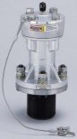
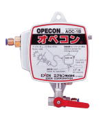
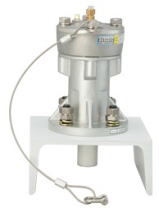
Air Knocker
Direct Type
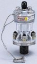
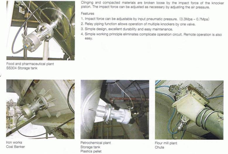
A piston strikes a wall by the force of a compressed air. It is the instrument which prevents adhesion and a blockade of a bulk material by the impact force Moreover, it can be used only by air feeding and excels in safety and economical efficiency. It is effective in a bulk material with the characteristic which will adhere when a vibration is given.
The stroke of the piston which moves, and the knocker itself are not moved, it can hit. A usage also spreads on idea. Moreover, it can use also like a indirect impact type.
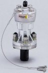
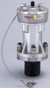
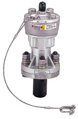
Indirect Type
A piston strikes a knocker`s body a base by the force of a compressed air.
It is the instrument which prevents adhesion and a blockade of a bulk material
by the impact force Moreover, it can be used only by air supply and excels
in safety and economical efficiency. It is effective in a bulk material
with the characteristic which will adhere to if a vibration is given.
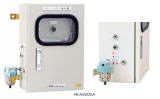
<Comparison between air knocker and piston vibrator>
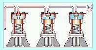
Compressed air is introduced to the air tank of the Knocker and
the piston momentarily works by opening/closing the inside valve
using three-way valve. The generated impact will avoid the powder
sticking/clogging problem at hoppers. This system eliminates the
manual hammering work. Fully automatic operation is possible.
Hammering strength is adjustable by changing pressure.
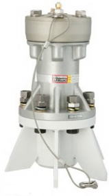
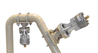
Multiple knockers can be installed by single valve action. Relay knocker Tubing for Multiple Air Knocker installation
When multiple installation, compressed air is supplied through three-way
valve to tank-center port of the knocker. And from the next sub port, another
tube is connected to the next air knocker main port. And the 3rd and more
knocker can be connected in the same way. All the air knockers work almost
at the same time (very short time lag). Multiple air knocker can be operated
by single valve action, which decreases the initial cost. Maximum quantity
(3 to 10 units) depends on the control and the three-way valve. (Patented)
EXAMPLE OF TYPICAL FLOW AID
SYSTEM INSTALLATION
Air knocker installation example
Examples of use on pipe
Pipe size
Pipe thickness (mm)
Recommended air knocker
3"
4.2
RKV30PA
4"
4.5
RKV40PA
5"
4.5
RKV40PA
6"
5
RKV40PA-RKV60PA
8"
5.8
RKV60PA
10"
6.6
RKV60PA
12"
6.9
RKV60PA
* The above is recommended for standard use.
* The model may change depending on the flowing material inside.
TROUBLE
PHENOMENON
.
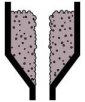
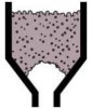
BRIDGING Bridging occurs when materials cling to the wall or compact above the discharge
opening of the lower part in the hopper, and the flow of materials in the
upper part is interrupted.
.
ARCHING
Arching occurs when materials in the lower part of the hopper flow out from the discharge opening, and an arch strong enough to support the entire head load in the hopper is formed
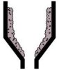
RATHOLING
Rat holing occurs when materials flow only above the exit, and form a tube
that leaves the hopper filled with "dead" materials, which will
not move.
ADHERENCE TO WALL
Clinging materials and also materials easily influenced by the moisture
and the temperature adhere to the wall and refuse to flow
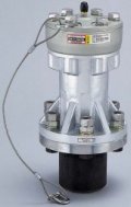
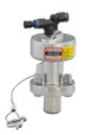
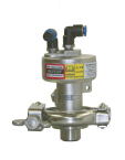
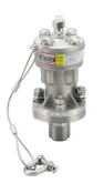
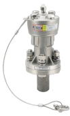
Indirect EXEN Air Knocker Models (carbon steel & stainless steel)
RKV20P
RKV30PA
RKV40PA
RKV60PA
RKV80PA
RKV100PA
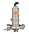
ferrule type
ferrule type
RKVS15
RKVS15-F
RKVS20
RKVS20-F
RKVS30
RKVS40 & 60
* RKVS30-F (ferrule type) is now available.
SPECIFICATIONS of indirect air knocker (carbon steel)
Model
Working Pressure
(MPa)
Percussion Cycle
(times/min)
Air Consumption
(Nl/time)
Percussion Energy
(N-m)
Impulsive Force
Total Weight
(kg)
(kg-m/s)
Suitable hammer (Ibs)
RKV20P
0.3-0.7
1-60
0.04-0.10
.4.3-8.3
0.6
below 1.0
0.7
RKV30PA
0.05-0.13
5.49-13.1
1.70-2.60
below 1.0
1.3
RKV40PA
0.15-0.37
9.22-22.3
2.86-4.42
1.0-1.5
3.4
RKV60PA
0.33-0.77
20.60-49.0
6.80-10.50
1.5-3.0
8.8
RKV80PA
0.60-1.40
45.10-109.0
15.00-23.30
3.0-8.0
13.7
RKV100PA
0.98-2.28
82.40-201.0
28.70-44.50
6.0-15.0
30.8
How to determine the recommended model/quantity from
hopper size & hopper plate thickness
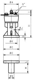
DIMENSIONS CHART(mm)
Model
A
C
D
G
H
I
J
K
L
M
N
RKV20P
57
57
6
1/8
70
(25)
6.5
44
6
28
21.7
RKV30PA
66
70
8
95
8.5
55
8
35
27.2
RKV40PA
86
95
12
140
12.5
70
13
60
34.0
RKV60PA
115
138
14
183
14.5
110
15
80
76.3
RKV80PA
146
148
16
1/4
222
(28)
17.0
120
18
90
RKV100PA
175
208
20
270
21.0
170
23
115
114.3
INSTALLATION METHOD
(1)
When wall thickness in the installation part is thin, prepare the
reinforcing plate of 3 2 to 6 mm thick, and weld the center and
around the whole reinforcing plate in front fillet welding to the
hopper for transmitting percussion force more efficiently.
REINFORCING
PLATE
DIMENSIONS
Model
Square
Plate
Round
Plate
RKV30PA
150*150 mm, t3.2
150 mm dia. t3.2
RKV40PA
200*200 mm, t3.2
200 mm dia. t3.2
RKV60PA
300*300 mm, t4.5
300 mm dia. t4.5
RKV80PA
400*400 mm, t4.5
400 mm dia. t4.5
RKV100PA
500*500 mm, t6.0
500 mm dia. t6.0
(2)
Weld around the whole circumference of the base.
(3) For the
model larger than RKV60, weld accessory reinforcing rib usually
necessary for RKV30P and 40P.
(4) Tighten the body thoroughly,
using accessory bolt, spring washer, and hard lock nut.
(5)
Secure the knocker by suspending with wire rope to prevent the
knocker from dropping.
CAUTION ON
WELDING
When operating, considerable impact is given to welds. When welding, pad as much as possible to eliminate damage, which may be caused.
 Please call AAAmachine
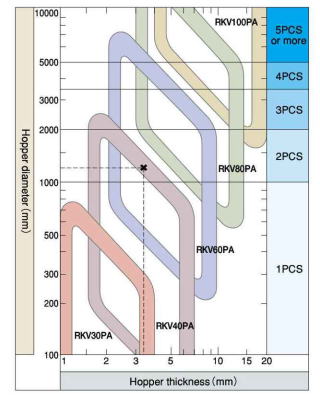
 Relay knocker
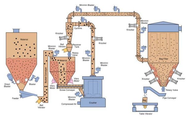
 .
. .
.